Spring-Mass-Damper Kit - Tutorial
Topics:
-
General Features and Quick Start
-
Example Experiment: Force Input Response (upon request)
-
Example Experiment: Spring Rate Coefficient Measurement (upon request)
-
Example Experiment: Sweep Frequency Response (Bode Plot) (upon request)
-
Example Experiment: PID Controller for Position Control (upon request)
-
Example Experiment: LQR Controller for Position Control (upon request)
Safety Guidelines
(updated on 4/16/2025)


Safety Guidelines
If improperly used, EMB can cause serious injuries!
Every user must read and understand the EMB Safety Manual before using this kit: EMB SAFETY MANUAL (MUST READ)

General Features and Quick Start
The EMB Spring-Mass-Damper Kit (SMD Kit) consists of 1 or more linear slides with optical linear encoder, an actuator with rack and pinion, one or more springs, one or more dashpots, mass blocks, hard stops, the optical breadboard and complementary components.

Before using the EMB system, ensure the following:
-
All users read the safety section above and are following safety precaution
-
The power supply to the amplifier is turned off
-
The E-STOP button is pressed to disable any potential motion
-
All components such as mass blocks, springs, and dashpots are properly installed and secured for motion
-
The hard stops are properly installed and tested by manually moving the linear slide
Follow the next procedures to run your experiment:
-
Step 1: Plug the EMB-DAQ to the computer
-
Step 2: With the E-STOP button still pressed (disabled), turn the amplifier power supply on. We recommend a setting of 12V and a current limit of 3A. The ESCON amplifier should turn on but be disabled (red LED)
-
Step 3: Start your software application (MATLAB® and Simulink® for example)
-
Step 4: Enable the E-STOP (turn to reset). The ESCON amplifier should still have a red LED, as the input signal (PWM) and the enable signal are not proper yet
-
Step 5: Run your code in the DAQ and be ready for motion
Immediately press the E-STOP in case of unexpected behavior or emergency
To turn off the system, follow these steps:
-
Press the E-STOP button
-
Turn-off the ESCON power supply
-
Close the software application (MATLAB® and Simulink® for example)
-
Either unplug the DAQ USB from the computer or turn the computer off completely. The DAQ LED should not be illuminated when not in use.
We strongly advise against leaving the EMB-DAQ and associated electronics powered on for extended periods, such as overnight.
While physically unplugging the USB from the computer or DAQ will power it off, it can cause wear to the USB connector over time. Therefore, turning off the USB port via software or shutting down the computer is the preferred method.
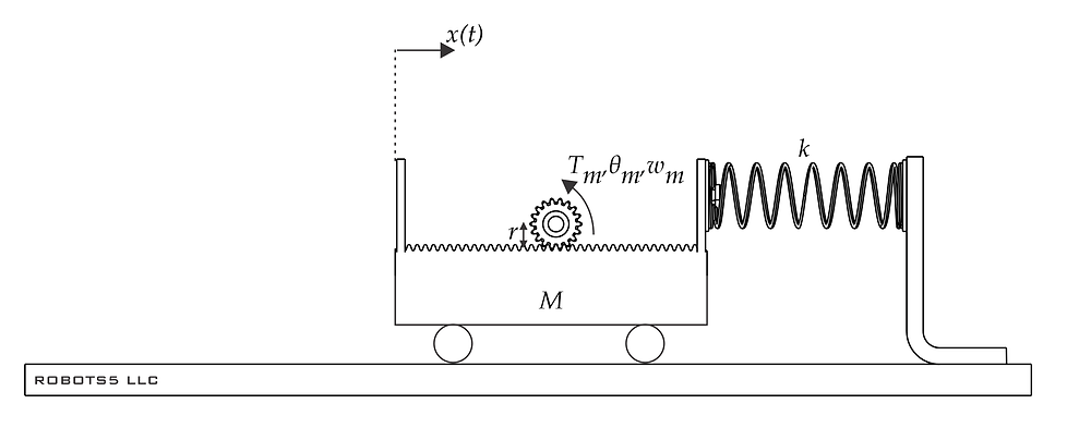
Drive System (Rack and Pinion)
An actuator (EMB-AM4 for example) drives a rack and pinion, applying a force to a carriage. The standard pinion we configure our kits is metric, stainless steel, has 20 teeth, and is module 20. The theoretical acting force radius is 0.01 m (pitch circle).
A small amount of backlash is present between the rack and the pinion gear. At our factory, we use precision gauges and fixtures to optimize the amount of backlash. At some point, you might have to adjust or reinstall the rack, in case it gets removed. Although potentially a bit tricky, this procedure can be performed by the use, there's no need to send any hardware to our factory.
If you wish to remove the actuator, for example to perform free vibration studies without the influence of the pinion and actuator dynamics, we recommend keeping the actuator clamped attached to the breadboard and loosening the dovetail instead, sliding the actuator backwards, disengaging the pinion from the rack. Doing it this way, the alignment of the motor assembly to the rack is still maintained for later installation.
Springs
Our spring kit comes with 4 stainless steel springs with the following nominal parameters:
-
Spring 1: rate 90 N/m, length: 85 mm
-
Spring 2: rate 225 N/m, length: 90 mm
-
Spring 3: rate 453 N/m, length: 75 mm
-
Spring 4: rate 812 N/m, length: 90 mm

A round stainless steel plate with an M5 thread is welded to each side of the springs. Our springs are symmetric (left and right are the same).
For typical Spring-Mass-Damper plants, one end of the spring is mounted to the moving carriage side plate and the other to a spring bracket. The same M5 fasteners are used with oversized washers (larger outside diameter only).
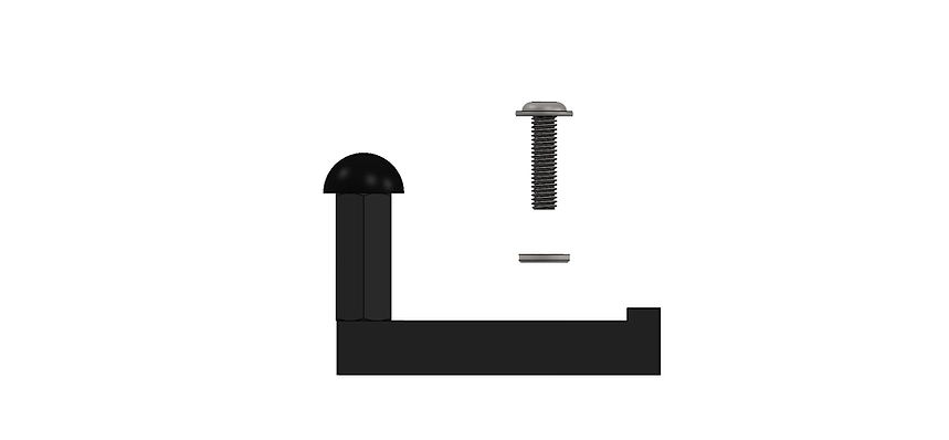
To secure the spring bracket to the breadboard, an M6 fastener and washer is used (orient the washer face with the rounded edge away from the anodized surface, so no surface damage occurs due to washer edge burrs):

A 4 mm hex tool is used to fasten both types of fasteners.
To ensure proper spring installation, avoid twisting the spring. Instead of fully tightening one side before the other, screw each side in incrementally. Once both sides are initially secured, slightly loosen the first side to relieve any rotational tension. Then, tighten it completely in its resting position.
With every spring, we include the nominal spring rate coefficient. For a more accurate value, a spring measurement experiment can be performed with the Spring-Mass-Damper Kit. We provide the code and instructions.
Below is a plot and experimental coefficients for one of our EMB springs:

As a reminder, when handling springs, be aware of the potential energy stored and the risk of sudden release.
Never exceed the recommended load or extension limits of our springs, this will damage the spring permanently.
Mass Blocks
To change the mass properties of the linear systems, the user can add or remove mass blocks. These blocks are machined brass measuring 2" by 2" by 1/2" with a 1/4" clearance hole in the center.
The finish is electroless nickel plate to provide the best wear and tear resistance.

The fastener is determined by the number blocks stacked (different lengths), the dovetail clamp and square nut are the same:


A 4 mm hex tool is used to fasten these M6 flanged button head fasteners.
To get an accurate mass parameter, we advise measuring with a scale each "mass assembly".
The nominal values are:
-
Dovetail only = 62 g
-
Dovetail, 1 Block, square nut, M6X22 fastener = 348 g
-
Dovetail, 2 Block, square nut, M6X35 fastener = 628 g
-
Dovetail, 3 Block, square nut, M6X45 fastener = 908 g
Don't forget to add the mass of the carriage, nominal 520 g.
Always make sure the mass blocks and dovetail clamp are firmly secured before running any experiment with EMB!
Dashpot
The dashpot is a delicate module, due to use of graphite piston, glass body, and aluminum rod with necked reliefs near the ball-joints (safety feature).
Our EMB dashpot has a limited stroke of 76 mm (approximately 3 inches). It is crucial that the dashpot module is not used as a hard stop for any EMB plant. End-of-travel collisions can cause permanent damage to the module. To prevent this, external hard stops must be implemented to limit travel.
For typical Spring-Mass-Damper plants, the moving rod side of the dashpot with a 10-32 stud is mounted to the carriage side plate by the 3/8" hex nut. We include a wrench with the dashpot assembly. During installation, hold the 10-32 stud with your finders while torqueing the 3/8" hex nut with the wrench.
Be careful not to bend or damage the moving rod (it has a necked portion near the ball joint) and the glass.
To secure the dashpot bracket to the breadboard, an M6 fastener and washer is used (orient the washer face with the rounded edge away from the anodized surface, so no surface damage occurs due to washer edge burrs):

When adding the dashpot module to your plant, make sure the moving rod and the body of the dashpot are as collinear as you can. Excessive misalignment will result in rapid wear and tear of this component.
To adjust damping, turn the knob clockwise to increase and counterclockwise to decrease damping. The nominal damping range is from 0-40 lbf-s/in, 0-7 N-s/mm.
The damping adjustment knob can be removed to provide the smallest amount of damping while the dashpot module is installed.
Do not completely close the dashpot as it will damage the device or can potentially break in a dangerous fashion!
Hard Stops and Limit Switches
The proper use of hard stops is critical to prevent permanent damage of the linear slides and/or dashpot module from an end of travel collision, by limiting the travel to a safe region.
The contact point on our hard stops have a durometer 70A rubber bumper. There should never be metal-to-metal contact!
To secure the hard stop to the breadboard, an M6 fastener and washer is used (orient the washer face with the rounded edge away from the anodized surface, so no surface damage occurs due to washer edge burrs):

The placement of the hard stops vary depending on your plant configuration and needs, we recommend at least 10 millimeters of buffer, between the internal hard stop of the linear slides (EMB-LM1 or EMB-LM2) and the external hard stop. Remember, the internal hard stops of the linear slides should never be used as system hard stops, as they are not meant for external loading, only internal to hold the bearing balls in place. Please refer to the EMB-LM1 manual for additional details.
As an optional module to our EMB plants, the end-of-travel switches (EoTS) provide additional capability to EMB. The main use is for safety as a limit switch - when one of the switches is triggered, a fault occurs and the system stops. Another potential application of the EoTS is for homing the carriage motion.
The only contact point of the switch and the moving carriage should be the switch lever.
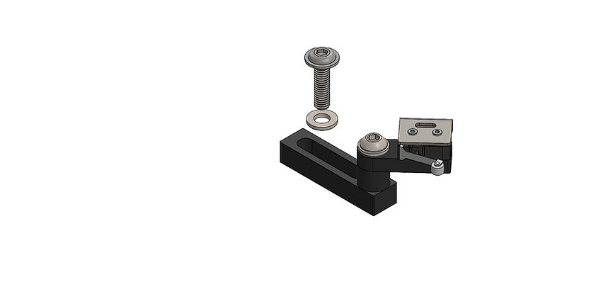
We offer a right and a left EoTS designed for each side of the linear slide.
To secure the hard stop to the breadboard, an M6 fastener and washer is used (orient the washer face with the rounded edge away from the anodized surface, so no surface damage occurs due to washer edge burrs):
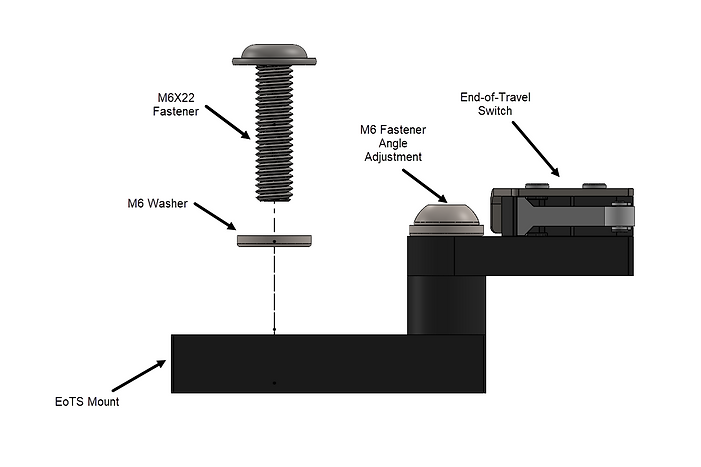
These EoTS should not be used as hard stops, this will cause permanent damage. The switches should be placed right before a hard stop. Make sure the switch opens (clicks) but the switch doesn't bottom out before hitting the hard stop.
For placement, you can make use of the mount slot and the angle adjustment M6 fastener. Make sure all fasteners are secured before running experiments and no cables are on the travel path (cables not shown in renders).
Example Experiment: Force Input Response
(updated on 4/13/2025)
EXAMPLE: Force Input Response
As a starting example, we will develop a model to apply a force to spring-mass-damper carriage. This is going to drive (pun intended!) many of the other examples and experiments!
We will be using an an EMB-SMD 1DOF kit, with actuator (EMB-AM4), a maxon ESCON amplifier in current mode (standard configuration), and an EMB-DAQ1 with MATLAB® and Simulink®.
You can download the model by clicking here: R5_EMB_SMDS_FORCE_INPUT.ZIP (50KB) or from our GitHub. Make sure to always use the latest version.
To run the model:
-
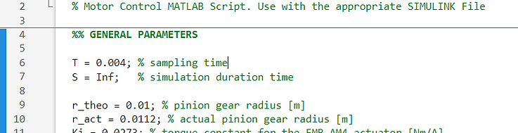
In the MATLAB® Command Window, enter the sampling time (T=0.002, for example) and simulation Stop Time (S=inf, for example).
-
In Simulink®, open R5_EMB_EXAMPLE_LED model open, enter the DESKTOP REAL-TIME tab, and click Run in Real-Time. If you run the model from the SIMULATION tab (green Run button), it won't work properly, and the EMB-DAQ1 will need to be reset. To reset the DAQ, power cycling the board is required by unplugging the USB cable and plugging back into the computer.
-
After clicking in Run in Real-Time, many processes take place, including building, code generation, and deployment of code to the target. These processes take between 5s and 20s.
-
To stop the model from running, you can click Stop in Simulink®.
To run the model:
-
In the MATLAB® Command Window, enter the sampling time (T=0.02, for example) and simulation Stop Time (S=5, for example). These variables can be incorporated into a MATLAB® Script (.m file) that runs before the Simulink® model. The maximum real-time sampling rate of this board is up to 1024 Hz. We recommend using sampling time between 0.001s to 0.010, depending on your model. Be careful with signal noise due to spatial quantization and excessive phase lag. We find a sampling time of about 0.004s is a good balance for our electro-mechanical plants.
-
In Simulink®, open R5_EMB_GENERAL model open, enter the DESKTOP REAL-TIME tab, and click Run in Real-Time. If you run the model from the SIMULATION tab (green Run button), it won't work properly, and the EMB-DAQ1 will need to be reset. To reset the DAQ, power cycling the board is required by unplugging the USB cable and plugging back into the computer.
-
After clicking in Run in Real-Time, many processes take place, including building, code generation, and deployment of code to the target. These processes take between 5s and 20s.
-
If the model doesn't run, check if the E-STOP or one of the End-of-Travel-Switches are pressed.
-
To stop the model from running, you can click Stop in Simulink®, press the E-STOP (if configured), press the End-of-Travel-Switch, or any logic fed into the Stop Simulation Block in Simulink®. We strongly recommend the use of these features to keep operation of EMB safe!